


3 Axis Waterjet Mixing Chamber – KAD-DD30 Cutting Head Part
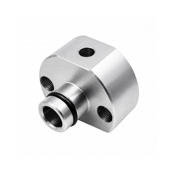
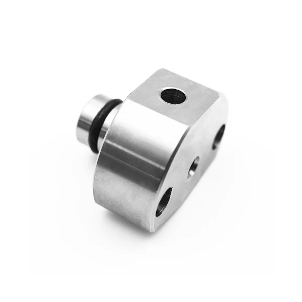
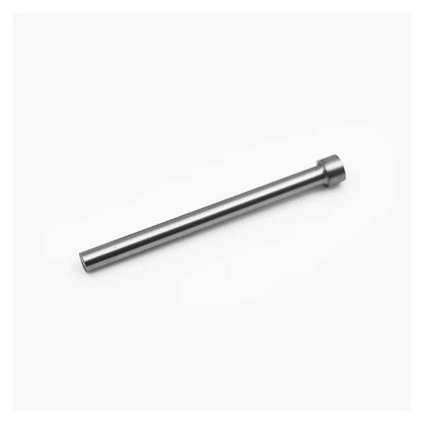
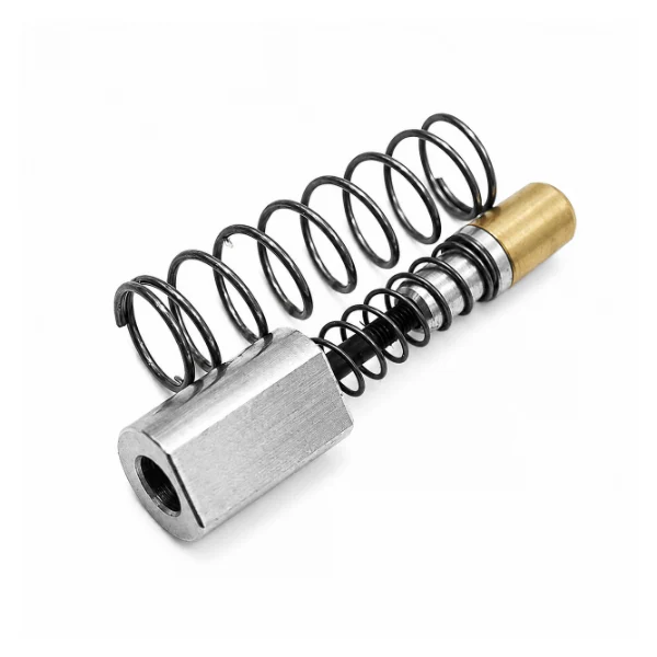
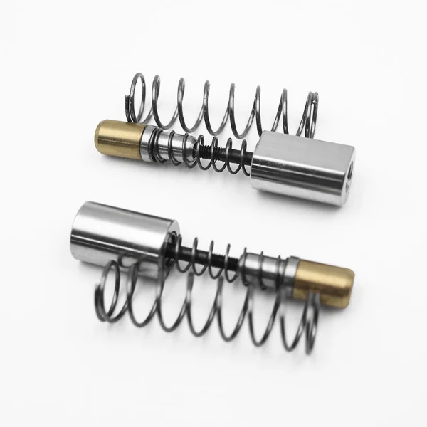
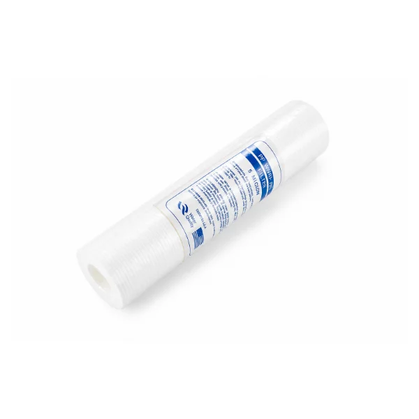
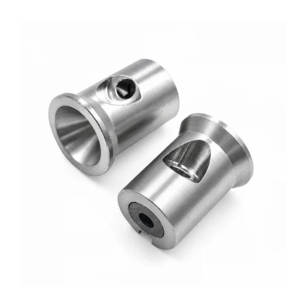
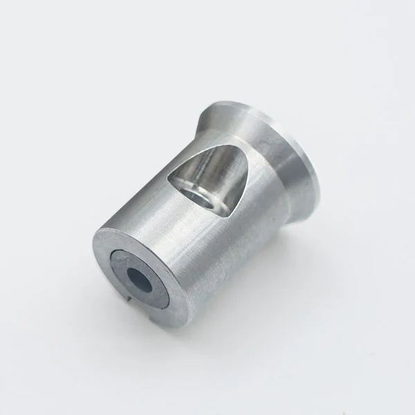
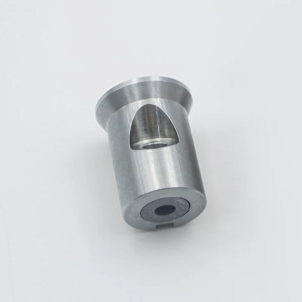
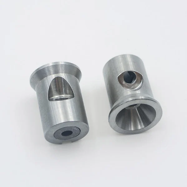
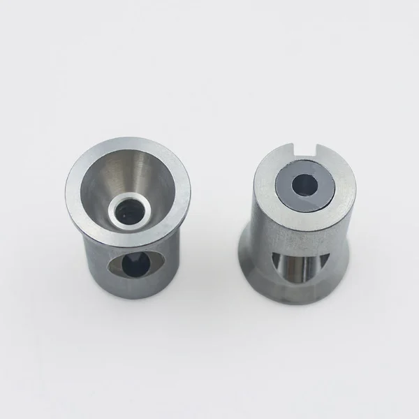
The KAD-DD30 3 Axis Waterjet Mixing Chamber is a replacement component for compatible three-axis abrasive waterjet cutting heads. The machined cylindrical body features side openings, an axial passage, and a flanged end visible in the product photographs. During cutting, the high-velocity waterjet draws abrasive particles into the mixing region before the mixture travels through the focusing tube. KAD supports industrial buyers requiring replacement mixing chambers, component identification, and drawing-based OEM parts sourcing.
- Machined Abrasive Flow Passage
- Compact Cylindrical Structure
- Orifice & Mixing Tube Interface
- Replacement Parts Support
Share:


- Description
- Specification
- Application
- FAQS
Description – Abrasive Mixing Chamber for 3-Axis Waterjet Cutting Heads
The KAD-DD30 mixing chamber is intended for the abrasive delivery section of compatible three-axis waterjet cutting equipment. It works together with the water orifice, abrasive feed connection, and focusing tube to form an abrasive cutting jet.
High-pressure water passes through the upstream orifice and becomes a high-velocity stream. As the jet enters the mixing region, it creates a local low-pressure area that draws abrasive particles into the flow path.
The abrasive particles are carried downstream into the focusing tube, where momentum is transferred from the water stream to the abrasive.
The KAD-DD30 component should be selected according to its actual dimensions, internal passages, and compatibility with the existing cutting head assembly.
Waterjet Mixing Chamber Working Principle
In a conventional abrasive waterjet cutting head, three main components contribute to jet formation:
- Water Orifice: Converts pressurized water into a concentrated high-velocity jet.
- Mixing Chamber: Provides the region where abrasive particles are drawn into the moving water stream.
- Focusing Tube: Accelerates and directs the abrasive-laden jet toward the workpiece.
KAD-DD30 belongs to the mixing chamber portion of this assembly. It should not be confused with the downstream focusing tube or the complete cutting head.
Internal Passage and Abrasive Entry
The KAD-DD30 product photographs show a metal cylindrical body with a side opening, a larger end cavity, and a smaller axial opening.
These features are relevant when identifying the component and reviewing its connection to the cutting head's abrasive and water flow paths.
The dimensions and internal geometry must correspond to the original design. Buyers should compare the existing part with technical drawings or confirmed replacement specifications.
Mixing Chamber Wear and Maintenance
Mixing chambers operate in an abrasive environment where garnet particles and high-velocity flow can gradually affect exposed internal surfaces.
During maintenance, technicians should inspect accessible openings for erosion, accumulated abrasive, cracking, or other visible damage.
Uneven abrasive delivery or abnormal cutting performance should prompt inspection of the complete cutting head assembly rather than immediate replacement of the mixing chamber alone.
Engineering Strength & Component Inspection
1. Internal Flow Passage Geometry
The relative positions of the axial passage and abrasive entry path are important features of a mixing chamber. The component should be evaluated against the approved drawing to confirm suitable passage dimensions and geometry.
2. Cylindrical Body and End Features
The outside diameter, overall length, flanged end, and end-face geometry are relevant to replacement selection. These features should be measured and compared with the original component.
3. Abrasive Wear Inspection
Internal surfaces and exposed entry openings should be checked for erosion, cracks, blockage, or dimensional changes that could affect the component's suitability for continued service.
4. Component Cleaning and Dimensional Verification
Before installation, the chamber should be checked for foreign material and visible damage. Critical dimensions and inspection requirements should follow the applicable technical drawing and cutting head manufacturer's instructions.
Why Choose KAD for KAD-DD30 Mixing Chamber Parts?
| Item | Specification |
|---|---|
| Product Code | KAD-DD30 |
| Product Type | 3-Axis Mixing Chamber |
| System Type | Waterjet Cutting Head |
| Function | Abrasive mixing & jet formation |
| Material | Stainless steel / wear-resistant alloy |
| Structure | Venturi mixing design |
| Operation | Continuous industrial use |
| Feature | Stable mixing performance |
| Application | Waterjet cutting systems |
1. Three-Axis CNC Waterjet Cutting Systems
KAD-DD30 is intended for mixing chamber replacement inquiries involving compatible three-axis abrasive waterjet cutting heads. Its suitability depends on the original nozzle assembly and component specifications.
2. Abrasive Jet Formation System Maintenance
The mixing chamber operates between the upstream orifice and downstream focusing tube. Maintenance work may involve checking the chamber for wear, contamination, or incorrect component positioning.
3. Mixing Chamber Wear Inspection and Replacement
During routine cutting head servicing, technicians can inspect the chamber's internal passages and external interfaces for damage. Replacement should be based on observed condition and the equipment manufacturer's acceptance criteria.
4. Orifice and Focusing Tube Assembly Servicing
When inspecting inconsistent abrasive flow or poor jet quality, maintenance teams should consider the condition of the water orifice, mixing chamber, abrasive feed path, and focusing tube together.
5. Waterjet Spare Parts Procurement
Equipment repair companies and parts distributors can reference KAD-DD30 when requesting suitable mixing chamber components. Drawings, measurements, and part photographs help clarify replacement requirements.
1. What is a 3 Axis Waterjet Mixing Chamber?
A 3 Axis Waterjet Mixing Chamber is a component used in compatible three-axis abrasive waterjet cutting heads. It provides the region where abrasive particles are drawn into the high-velocity waterjet before entering the focusing tube. The three-axis designation refers to the cutting machine configuration rather than moving axes within the chamber.
2. How does the KAD-DD30 mixing chamber work?
High-pressure water passes through an upstream orifice to create a high-velocity jet. As the jet enters the mixing region, it creates suction that draws abrasive particles into the flow path. The abrasive-laden stream then travels through the focusing tube toward the cutting area.
3. What is the difference between a mixing chamber and a mixing tube?
The mixing chamber introduces abrasive particles into the waterjet, while the mixing tube, also called the focusing tube, is positioned downstream to accelerate and direct the abrasive-laden stream. These components perform different functions and should not be treated as interchangeable replacement parts.
4. What are the common signs of mixing chamber wear?
Possible signs include visible erosion around the abrasive entry path, damaged internal surfaces, accumulated abrasive, or abnormal component condition. Irregular abrasive suction may also involve the orifice, feed hose, or focusing tube, so the entire cutting head should be inspected before identifying the cause.
5. Can KAD-DD30 replace a 4-axis or 5-axis mixing chamber?
Compatibility cannot be determined from the number of machine axes alone. KAD-DD30 and KAD-DD31 are different product references, and their dimensions or interfaces may differ. Buyers should verify the cutting head model, original component drawing, and installation requirements before considering any replacement.
6. What information is required to order a KAD-DD30 mixing chamber?
Customers should provide the waterjet cutting head manufacturer, machine model, original component reference, and available photographs or drawings. Important details include the overall dimensions, relevant openings, mounting interfaces, material requirements, and purchasing quantity. KAD can use this information to evaluate replacement or OEM manufacturing inquiries.