


Mixing Chamber Body – Side-Inlet Waterjet Cutting Head Part
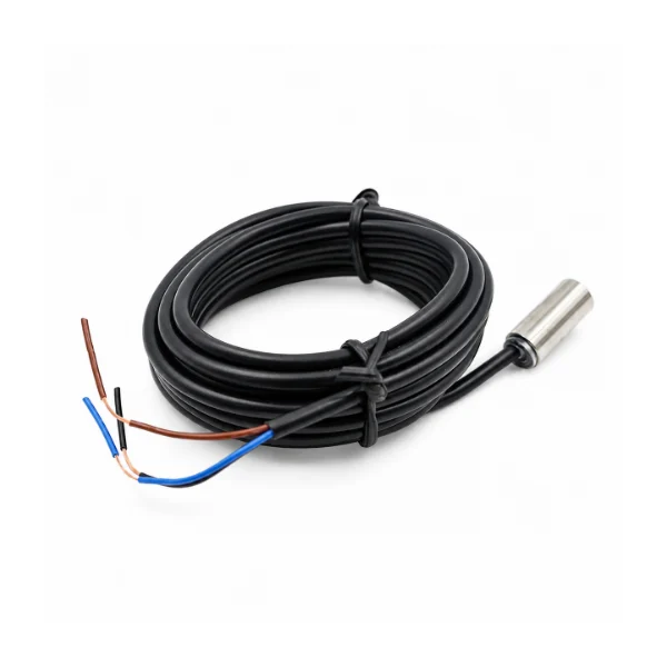
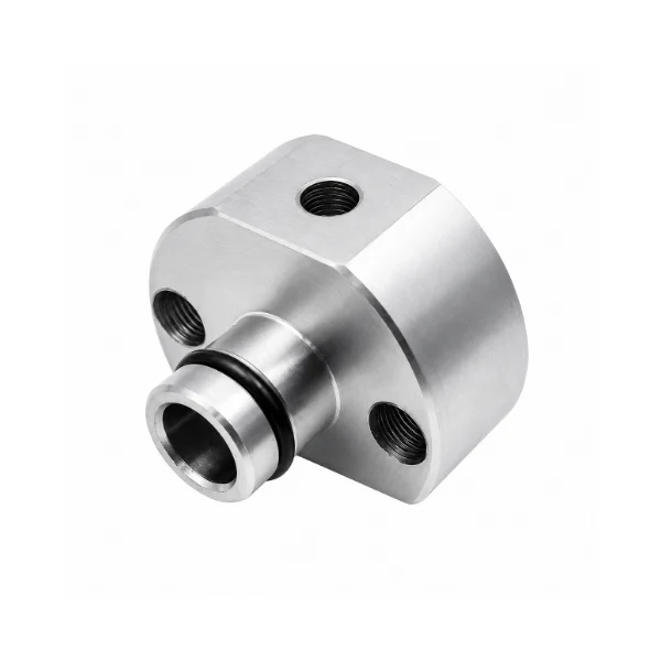
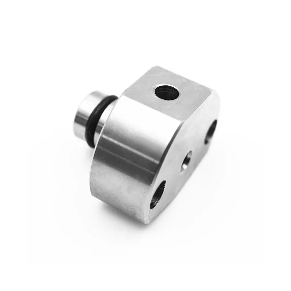
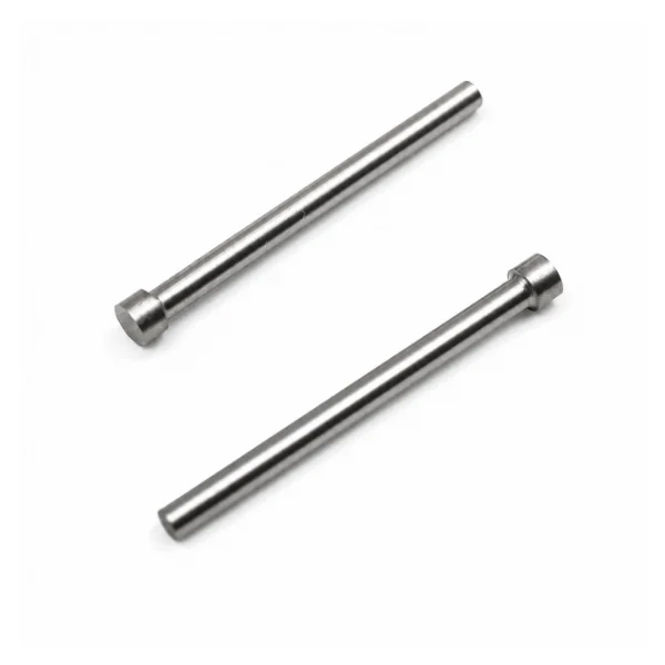
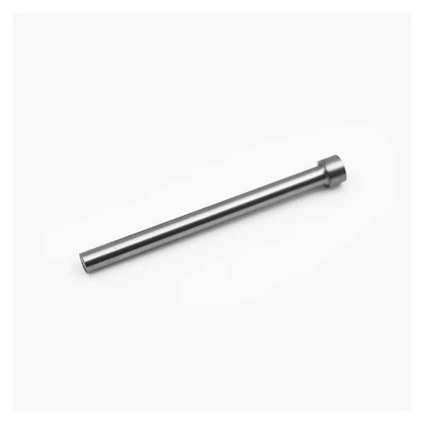
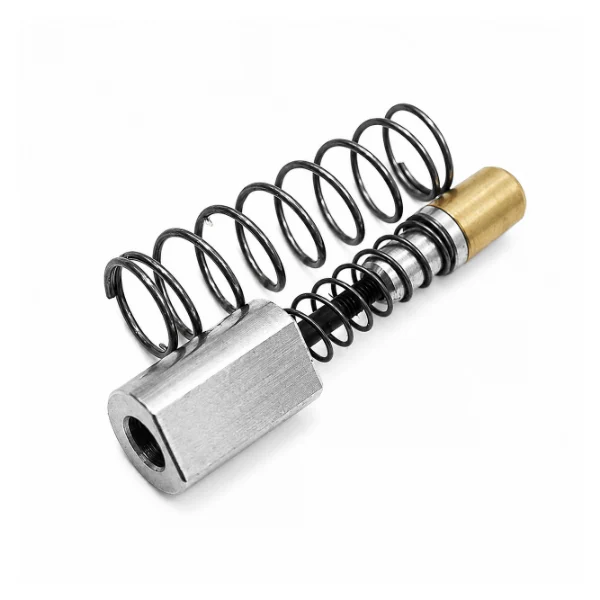
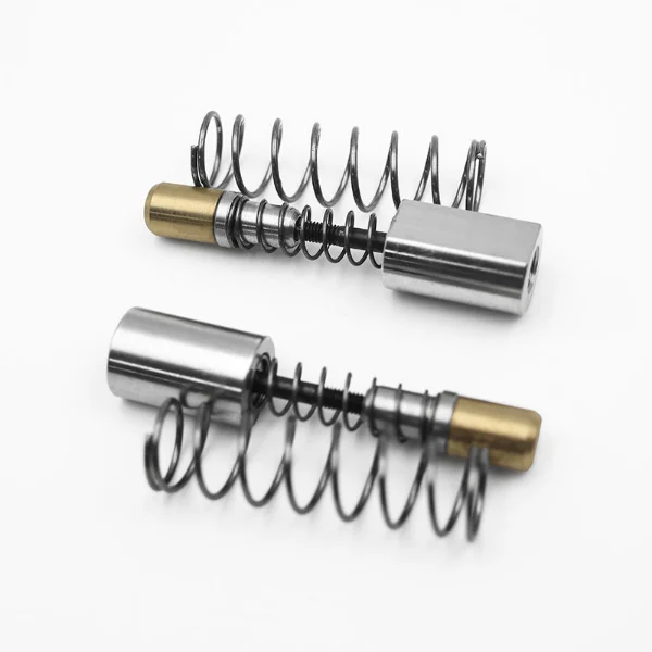
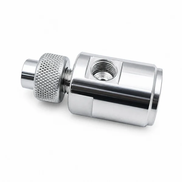
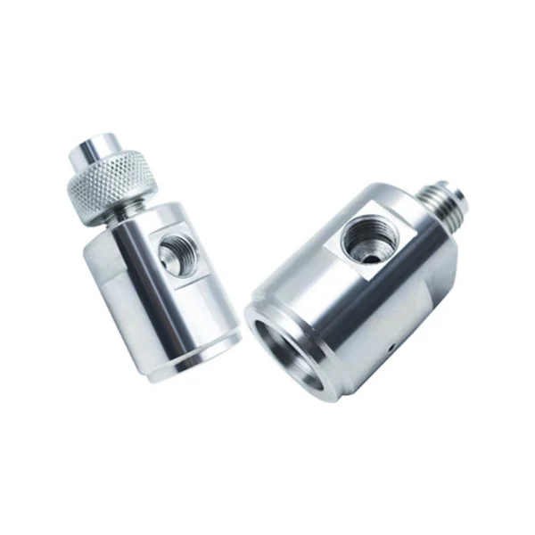
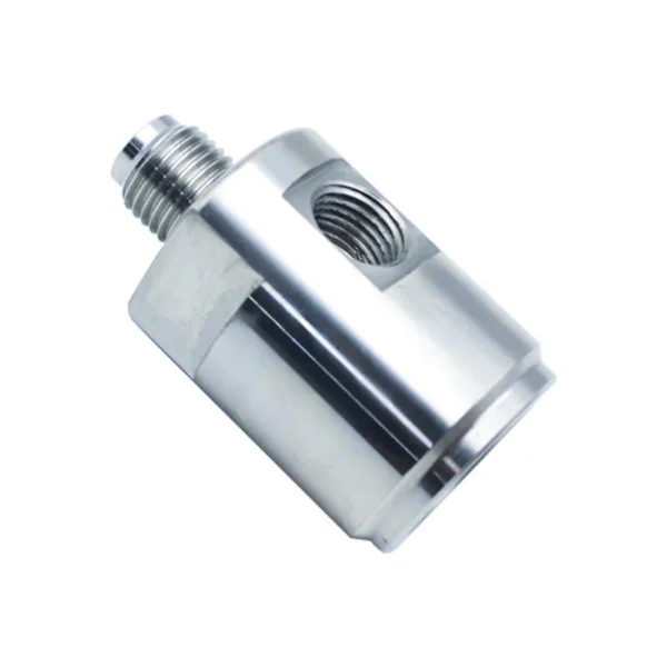
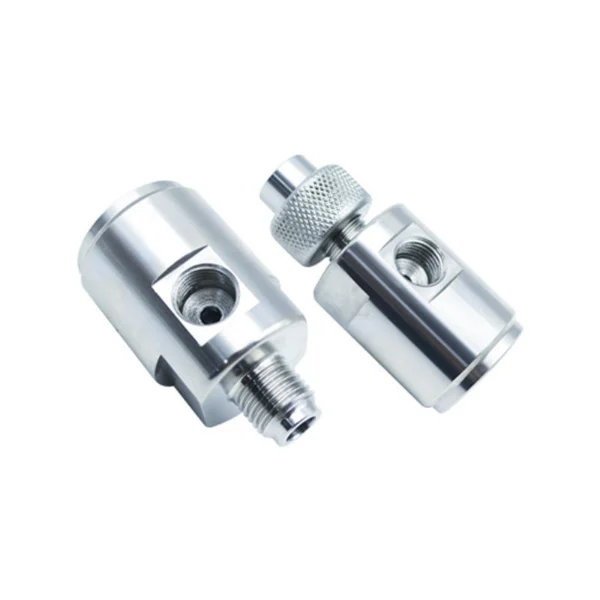
Body of Mixing Chamber is a included fabricated metal body for suitable abrasive waterjet cutting heads. The images of the product depict cylindrical containers with a threaded port on the side and openings at both ends, along with some external connection components. Additional pictures with different configurations involve a knurled end collar. The mixing chamber body offers the required connection and passage configuration for the original nozzle assembly in an abrasive cutting head. Replacement selecting involves confirmation of the port function, lengths and diameters of the threads, geometry of the housing, the mounting components involved, and compatibility of the cutting head.
- Side Threaded Port Design
- Machined Cylindrical Chamber Housing
- Axial Connection and Mounting Interfaces
- Multiple Component Configurations
Share:


- Description
- Specification
- Application
- FAQS
Description – Mixing Chamber Body Structure and Connections
A mixing chamber body is a mechanical component used within a compatible abrasive waterjet cutting head assembly.
Its function depends on the original equipment design, including the configuration of the waterjet passage, abrasive feed connection, and adjoining nozzle components.
The KAD product gallery displays silver-colored machined cylindrical bodies with side threaded openings, axial connection features, and flat-sided mounting surfaces.
Some photographs also show a knurled collar fitted to one end of the component.
These visible characteristics distinguish the product from a standalone focusing tube, ruby orifice, or simple nozzle retaining nut.
When purchasing a replacement body, customers should verify the actual installation position, original part number, side-port thread, axial connection dimensions, and the required supply configuration.
Side Threaded Inlet Port
One of the most distinctive features of the photographed component is the threaded opening located on the side of the cylindrical housing.
In compatible abrasive waterjet cutting head designs, a side inlet may connect the abrasive feed line to the mixing chamber.
The exact function of the KAD side port must be confirmed using the original assembly drawing.
Important identification parameters include:
- Side-port thread diameter
- Thread pitch and connection standard
- Port orientation
- Thread engagement depth
- Internal passage configuration
- Compatible inlet fitting or connector
The connection should match the specified abrasive feed component without unauthorized modifications.
A visually similar chamber body may use a different side-port thread and may not be interchangeable.
Axial Opening and Internal Passage
The photographed metal housing has a larger axial opening at one end and another connection feature at the opposite end.
These features are relevant to identifying the intended mounting arrangement.
Depending on the original design, the axial interfaces may correspond to associated cutting head components or their designated mounting positions.
The internal passage geometry cannot be fully determined from external photographs alone.
Customers should confirm the axial bore dimensions, interface depth, seat geometry, and original assembly configuration before ordering.
These requirements are more useful for replacement matching than a general description of the materials a waterjet machine can cut.
External Threads and Machined Flats
The product photographs show an externally threaded connection on one configuration of the chamber body.
Machined flats are also visible along parts of the cylindrical housing.
These features may provide connection and tool-engagement surfaces according to the original equipment design.
The applicable thread diameter, pitch, connection method, and tightening instructions must be verified against the manufacturer's documentation.
A replacement housing should match the original connection dimensions and mounting clearance.
The external appearance alone does not confirm the pressure rating or the complete internal sealing arrangement.
Mixing Chamber Body vs. Complete Mixing Chamber
A mixing chamber body and a complete mixing chamber assembly are not automatically the same product.
The body refers to the principal housing or machined component.
A complete assembly may include additional inserts, inlet components, retaining hardware, or other parts specified by the original equipment manufacturer.
The required components and assembly structure vary by cutting head design.
Customers should specify whether they need only the chamber body or the complete assembly shown in their original equipment parts list.
KAD can review reference photographs, part numbers, and drawings to help clarify the requested supply scope.
Replacement Identification Checklist
Before selecting a mixing chamber body, industrial buyers should compare the original component with the proposed replacement.
| Identification Item | Information Required | Purpose |
|---|---|---|
| Original Part Number | OEM or existing supplier reference | Confirms product identity |
| Cutting Head Model | Manufacturer and model | Identifies the correct assembly |
| Side Port | Thread diameter, pitch and position | Checks inlet connection compatibility |
| Axial Opening | Bore diameter and interface geometry | Checks adjoining component fit |
| External Connection | Thread size and end configuration | Verifies mounting connection |
| Housing Dimensions | Overall length and outside diameter | Checks installation space |
| Machined Flats | Flat-to-flat dimensions | Identifies housing geometry |
| Knurled Collar | Included or excluded | Clarifies the supply configuration |
| Material | Original material specification | Confirms manufacturing requirements |
| Assembly Scope | Body only or complete assembly | Prevents incorrect ordering |
The original equipment specification should be used to verify final replacement suitability.
Why Choose KAD for Mixing Chamber Body Parts?
| Item | Specification |
|---|---|
| Product Type | Waterjet Nozzle Body |
| System Type | Automatic Waterjet Cutting Machine |
| Function | Jet formation and flow control |
| Cutting Type | Pure waterjet / abrasive waterjet |
| Working Pressure | Up to 60,000 PSI / 420MPa |
| Material | Stainless steel / hardened alloy steel |
| Manufacturing Process | CNC precision machining |
| Supply Type | Wholesale / OEM / replacement parts |
| Application | Industrial metal cutting systems |
1. Abrasive Waterjet Cutting Head Maintenance
A mixing chamber body may require inspection or replacement during maintenance of a compatible abrasive waterjet cutting head.
The required component should be identified using the original equipment model, housing dimensions, and approved mounting arrangement.
2. Abrasive Inlet Connection Matching
Where the side opening serves as an abrasive feed connection, its thread and mating inlet fitting must be compatible with the specified cutting head.
A replacement part should not be selected solely because the side port appears similar to an existing component.
3. Chamber Housing and Thread Inspection
Maintenance personnel may inspect the housing for damaged threads, worn or damaged connection surfaces, deformation, and visible contamination.
Internal passages and contact surfaces should be assessed according to the original manufacturer's maintenance requirements.
4. Mixing Chamber Assembly Reconfiguration
Some cutting heads use specific combinations of chamber housing, retaining components, abrasive inlets, and adjoining nozzle parts.
When replacing only the body, the buyer should confirm whether existing components can be reused under the original equipment requirements.
Parts from different assembly variants should not be combined without verified compatibility.
5. Industrial Cutting Head Parts Procurement
Waterjet service providers and spare parts distributors may require replacement chamber bodies for ongoing equipment maintenance.
KAD can review the supplied technical references, component photographs, and quantity requirements to clarify the requested parts.
1. What is a Mixing Chamber Body in an abrasive waterjet cutting head?
A Mixing Chamber Body is the machined housing component of a designated abrasive waterjet mixing arrangement. Depending on the original design, it provides the mounting and passage interfaces for the waterjet and abrasive feed system. The KAD product photographs show a cylindrical metal housing with a side threaded opening and axial connections, although its precise internal configuration must be verified.
2. Is the side threaded port used for abrasive inlet connection?
In many abrasive waterjet cutting head designs, a side port is used to connect the abrasive feed line to the mixing chamber. The KAD product photographs show a side threaded opening, but the original drawing is required to verify its actual function. Buyers should confirm the port thread, connection fitting, and equipment model before ordering.
3. What is the difference between a mixing chamber body and a complete mixing chamber assembly?
The mixing chamber body refers to the housing component, while a complete mixing chamber assembly may include additional inserts, inlet fittings, retaining components, or other manufacturer-specified parts. The exact supply scope depends on the product design. Customers should identify whether they require the housing alone or the complete assembly listed in their equipment documentation.
4. What does the knurled collar shown in some product images do?
The knurled collar is a visible feature of one photographed component configuration. Its exact function cannot be established from the external images alone. It may relate to a particular assembly or connection arrangement, but buyers should confirm its purpose, whether it is included, and the applicable part number before purchasing.
5. Can this mixing chamber body replace a 3-axis, 4-axis, or 5-axis waterjet mixing chamber?
Compatibility cannot be determined from the machine's axis count alone. Different cutting heads may use different housing sizes, abrasive inlet positions, threaded connections, and assembly designs. The original cutting head model, part number, and dimensional requirements must be verified before selecting a replacement.
6. What information should I provide when ordering a mixing chamber body?
Please provide the cutting head manufacturer and model, original part number, photographs, side-port thread size, external connection details, overall dimensions, and purchasing quantity. If available, include the original assembly drawing and specify whether the required product includes the knurled collar or other components.