


Waterjet Hydraulic Relief Valve – KAD-TY044 Oil Circuit Part
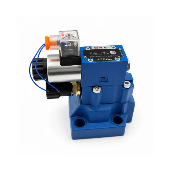
The KAD-TY044 WaterJet Hydraulic Relief Valve is a hydraulic pressure-control valve designed for use in water Jet hydraulic intensifier systems when the waterJet system is inplied. The image shows a hydraulic valve assembly consisting of a blue electrically operating valve body, a solenoid housing with a cylindrical shape, an electrical connector, and a product identification plate. It is used for hydraulic pressure limiting and relief. Before ordering a replacement, buyers should verify the original (OEM) valve model, pressure setting range, hydraulic port configuration, electrical specifications, and require the valve to meet any or all requirements.
- Hydraulic Pressure Relief Control
- Solenoid-Equipped Valve Assembly
- Blue Metal Valve Body
- Replacement Parts Matching
Share:


- Description
- Specification
- Application
- FAQS
Description – Hydraulic Pressure Relief in Waterjet Intensifier Systems
The KAD-TY044 hydraulic relief valve is intended for the hydraulic pressure-control section of compatible waterjet intensifier pumps.
In a hydraulically driven waterjet intensifier, pressurized hydraulic oil drives a piston that transfers mechanical force to the water-pressurizing plungers.
The hydraulic circuit requires appropriate pressure-control components to maintain pressure within the limits specified by the equipment manufacturer.
A hydraulic relief valve provides a pressure-limiting function by allowing oil to flow through a designated relief path when the applicable control condition is reached.
Depending on the specific valve design, pressure relief, unloading, or electrically controlled operating functions may be incorporated into the assembly.
KAD-TY044 should be identified using its original manufacturer reference and hydraulic specifications before replacement.
Pressure Limiting and Relief Operation
A hydraulic relief valve is used to limit pressure in a hydraulic system according to its specified operating characteristics.
In a conventional pressure relief arrangement, the valve allows hydraulic oil to pass through the designated relief circuit when pressure reaches the specified setting.
This helps prevent pressure from exceeding the intended hydraulic circuit limits, provided the complete system is correctly designed and maintained.
The actual pressure setting range, relief flow capacity, and operating characteristics must be established from the KAD-TY044 valve specification.
The visible electrical component also makes it important to determine whether this particular assembly has an electrically controlled unloading or pressure-setting function.
Solenoid Assembly and Electrical Requirements
The KAD-TY044 product photograph shows a cylindrical solenoid component mounted on the valve assembly, together with a transparent electrical connector.
These visible features indicate that electrical compatibility should be included in replacement identification.
Before selecting a valve, buyers should verify the coil voltage, AC or DC requirements, connector configuration, and relevant control functions.
The electrical actuation method and its relationship to the pressure-control mechanism must be confirmed from the original valve documentation.
A solenoid-equipped relief valve should not be assumed to have the same electrical behavior as a standard directional control valve.
Hydraulic Ports and Mounting Interfaces
The valve body forms part of the hydraulic connection arrangement and must match the intended hydraulic manifold or mounting assembly.
Important considerations include port configuration, mounting dimensions, connection standards, sealing interfaces, and available installation clearance.
The product photograph shows a blue valve assembly with visible circular openings and external mounting features.
However, the functions of the individual hydraulic ports cannot be established reliably from the photograph alone.
Customers should compare the original hydraulic symbol, port layout, and mounting drawings when evaluating KAD-TY044 replacement compatibility.
Hydraulic Relief Valve vs. Directional Control Valve
A hydraulic relief valve and a directional control valve perform different functions within a waterjet intensifier.
The relief valve is associated with hydraulic pressure limitation or relief, while the directional control valve changes the routing of hydraulic oil to control actuator movement.
In an intensifier system, both functions may be required, but they are handled by components selected for different hydraulic operating characteristics.
The KAD-TY044 valve should therefore not be confused with the KAD-TY045 directional control valve.
Main Functions – KAD-TY044 Hydraulic Relief Valve
- Provides a hydraulic pressure-limiting function within the specified circuit.
- Allows pressure relief through the designated flow path according to the valve design.
- Supports the hydraulic pressure-control arrangement of compatible waterjet intensifiers.
- Requires the correct relief setting, flow capacity, and mounting configuration.
- Must be matched to the original electrical controls where applicable.
Engineering Strength & Technical Inspection
1. Pressure Setting and Relief Function Verification
The specified pressure setting or adjustment range is a critical consideration for hydraulic relief valve selection.
The required operating pressure, relief capacity, and hydraulic control characteristics should be checked against the original valve documentation.
Any adjustment or functional testing must follow the equipment manufacturer's approved procedures.
2. Hydraulic Port and Mounting Inspection
The valve's hydraulic connection pattern and mounting geometry must correspond to the intended installation.
Inspection requirements may include port locations, mounting hole positions, mating surfaces, and sealing interfaces.
The original hydraulic drawing or manufacturer datasheet should be used to confirm these details.
3. Solenoid and Electrical Connection Review
Where electrical control is incorporated into the valve assembly, the solenoid and connection specifications must match the original equipment.
Relevant information includes coil voltage, power supply type, connector design, wiring requirements, and the defined electrical operating function.
Electrical components should be inspected for visible damage before installation.
4. Valve Body and Sealing Surface Inspection
The valve body, accessible connection surfaces, electrical housing, and identification plate should be inspected for damage or deterioration.
Hydraulic leakage, contamination, damaged seals, and unsuitable mounting interfaces may affect the operation of the assembly.
Any inspection, pressure testing, or acceptance requirements should be based on the approved valve specification.
Why Choose KAD for Hydraulic Relief Valve Parts?
| Item | Specification |
|---|---|
| Product Code | KAD-TY044 |
| Product Type | Waterjet Overflow Valve |
| System Category | Waterjet Valves & Pipe |
| Function | Pressure control & overflow protection |
| Working Condition | High-pressure industrial operation |
| Material | High-strength stainless steel / alloy steel |
| Manufacturing Process | Precision machining |
| Feature | Stable pressure release response |
| Application | Waterjet cutting machine systems |
1. Intensifier Hydraulic Pressure Limitation
A hydraulic relief valve is used in the pressure-control arrangement of compatible waterjet intensifier systems.
Its suitability depends on the circuit's hydraulic operating pressure, required relief characteristics, and correct valve installation.
2. Hydraulic Relief Valve Replacement
Replacement may be required when an existing pressure-control valve is damaged, fails inspection, or no longer meets the equipment manufacturer's operating requirements.
The replacement must match the original valve's hydraulic function, pressure specification, flow capacity, electrical configuration, and mounting interface.
3. Hydraulic Pressure Fault Diagnosis
Abnormal hydraulic pressure behavior can be associated with pressure-control components, hydraulic pumps, control signals, oil contamination, or other circuit faults.
The relief valve should be evaluated as part of the complete hydraulic system rather than assumed to be the cause of every pressure problem.
4. Waterjet Intensifier Maintenance
During scheduled maintenance, technicians may inspect the relief valve, external electrical connections, hydraulic interfaces, and accessible sealing areas.
Pressure-related inspections and adjustments must follow the approved hydraulic schematic and equipment safety procedures.
5. Replacement Parts and Industrial Procurement
Waterjet repair companies, hydraulic maintenance providers, and industrial distributors can request compatible relief valve assemblies using original component information.
Providing nameplate photographs, pressure specifications, hydraulic symbols, connection details, and required quantities helps clarify the replacement requirements.
1. What is a Waterjet Hydraulic Relief Valve?
A Waterjet Hydraulic Relief Valve is a pressure-control component used in the hydraulic circuit of compatible waterjet intensifier pumps. It provides a pressure-limiting or relief function according to the system design and valve specifications. The KAD-TY044 is listed for this application, with its exact pressure-control configuration requiring manufacturer verification.
2. How does a hydraulic relief valve work in a waterjet intensifier?
A hydraulic relief valve limits circuit pressure by allowing oil to pass through a designated relief path when the specified control condition is reached. In a conventional pressure relief system, this occurs when hydraulic pressure reaches the valve setting. The actual operation depends on the valve design and may include electrical unloading or control functions.
3. What is the difference between a hydraulic relief valve and a directional control valve?
A hydraulic relief valve controls pressure limitation or relief, while a directional control valve changes hydraulic oil flow paths to control actuator movement. In waterjet intensifiers, the two valve types perform separate functions and cannot be considered interchangeable based solely on their appearance or installation location.
4. Does the KAD-TY044 relief valve require an electrical connection?
The KAD-TY044 product photograph shows a solenoid housing and an electrical connector, indicating that electrical specifications are relevant to replacement selection. However, the exact coil voltage, switching behavior, and relationship between the solenoid and hydraulic relief function must be confirmed from the original valve datasheet.
5. What should I check if a waterjet hydraulic relief valve is not operating correctly?
Check the hydraulic pressure readings, valve model, electrical supply where applicable, hydraulic fluid condition, and related circuit components. Pressure abnormalities may also involve pumps, sensors, or other valves. Qualified technicians should follow the manufacturer's hydraulic schematic and safety procedures when diagnosing pressure-control problems.
6. What information is needed to order a KAD-TY044 hydraulic relief valve?
Provide the original valve model, nameplate photograph, waterjet pump information, pressure setting or adjustment range, hydraulic port configuration, mounting dimensions, and electrical specifications where applicable. Technical drawings and purchase quantities can help KAD evaluate replacement compatibility and prepare a quotation.